Online Blog > Previous Entry 12/15/2020 > 2/28/2021 - Slab preparation, pour and finish followed by wall framing.
After we finished pouring the basement walls and then stripped the forms,
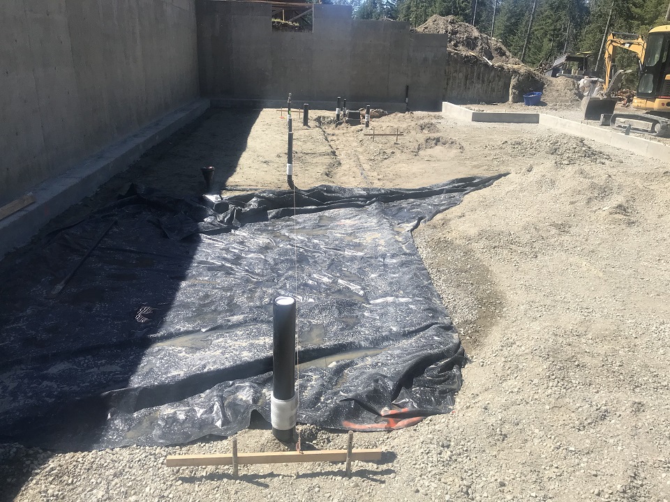
the very next step was to dig some trenches for the under-slab plumbing.
This is the drain, waste and vent side of the plumbing work that will be in
the ground and needs to be in place before we pour the slab. It will be
located such that the basement level fixtures will be accommodated, but also
the plumbing drops from the main floor above will penetrate this slab in the
correct locations.
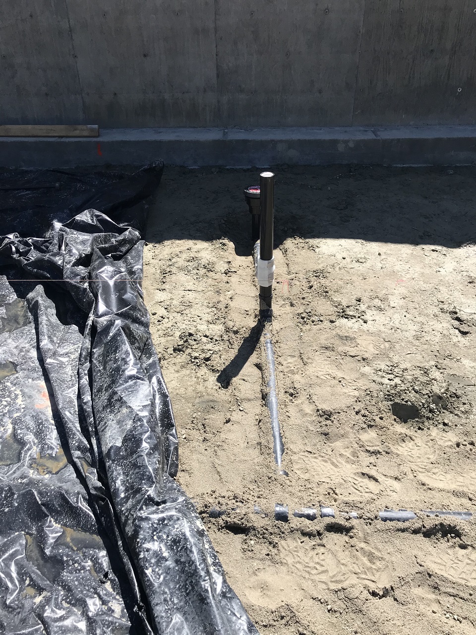
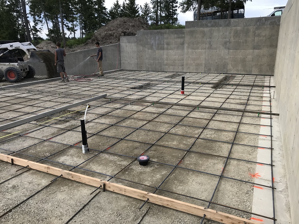
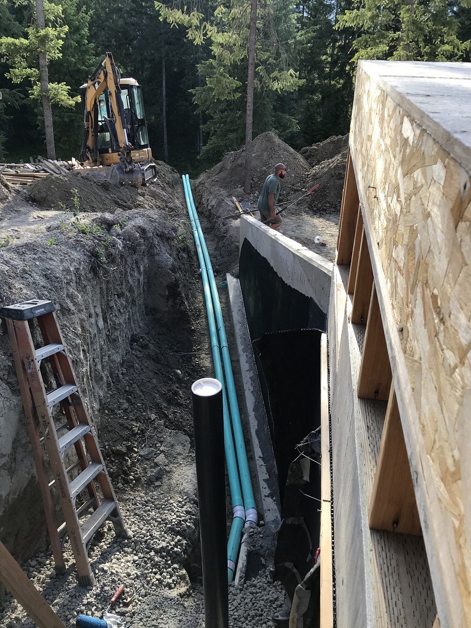
In the below photo you can see a floor drain and a riser. The riser is wrapped in some bubble plastic (we typically use sill sealer) to insulate the plastic pipe as it passes through the concrete slab. That way it has some cushion for expansion and contraction within the concrete. We brought in some sand to cover the plumbing and weigh it down and hold it in place before we compacted a rock sub-base upon which to pour the slab.
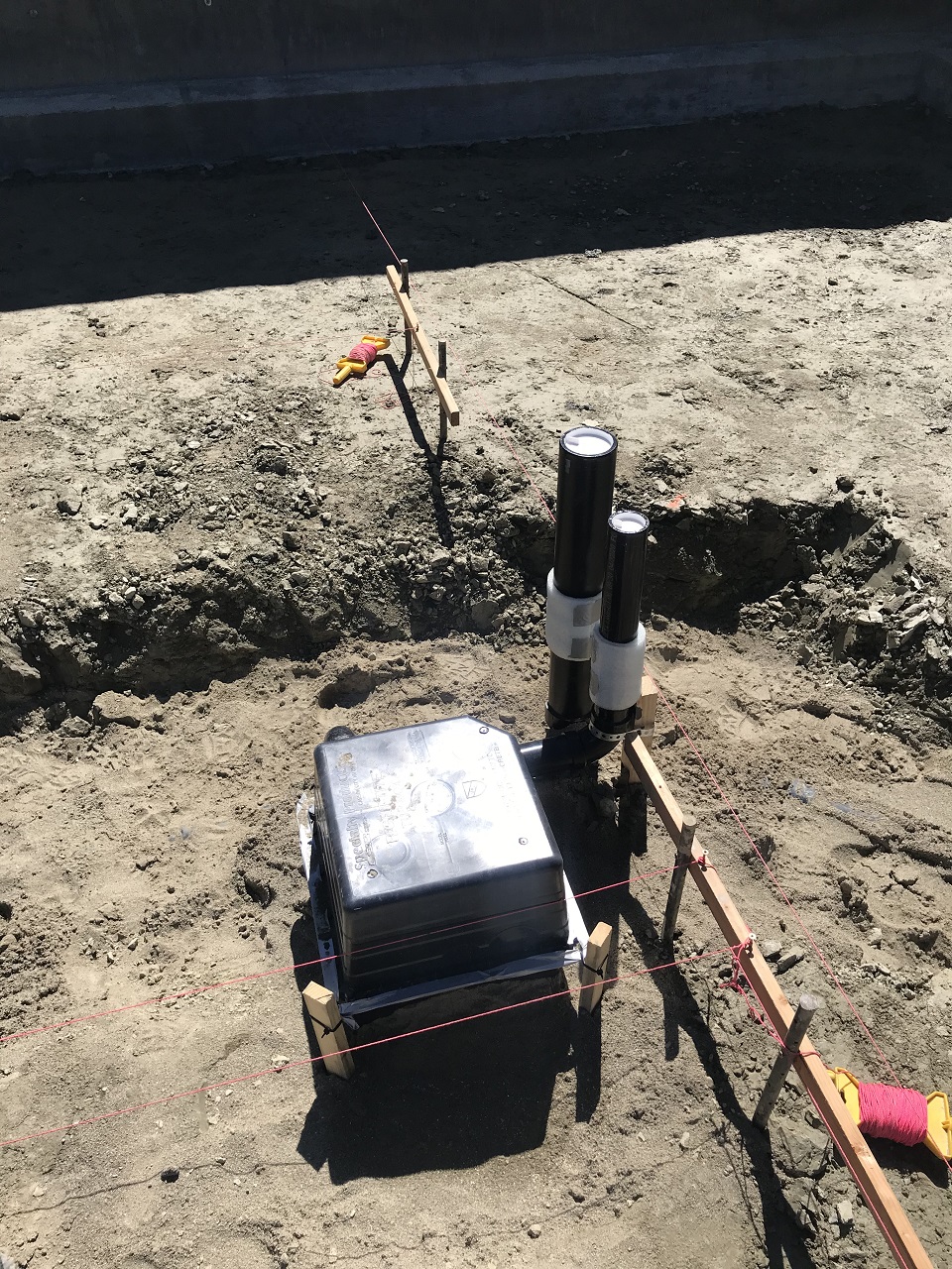
The below is a tub box. Essentially it creates a square void in the concrete slab in the area of a tub or shower drain to give room to connect the tub later to a p-trap and the drain pipe.
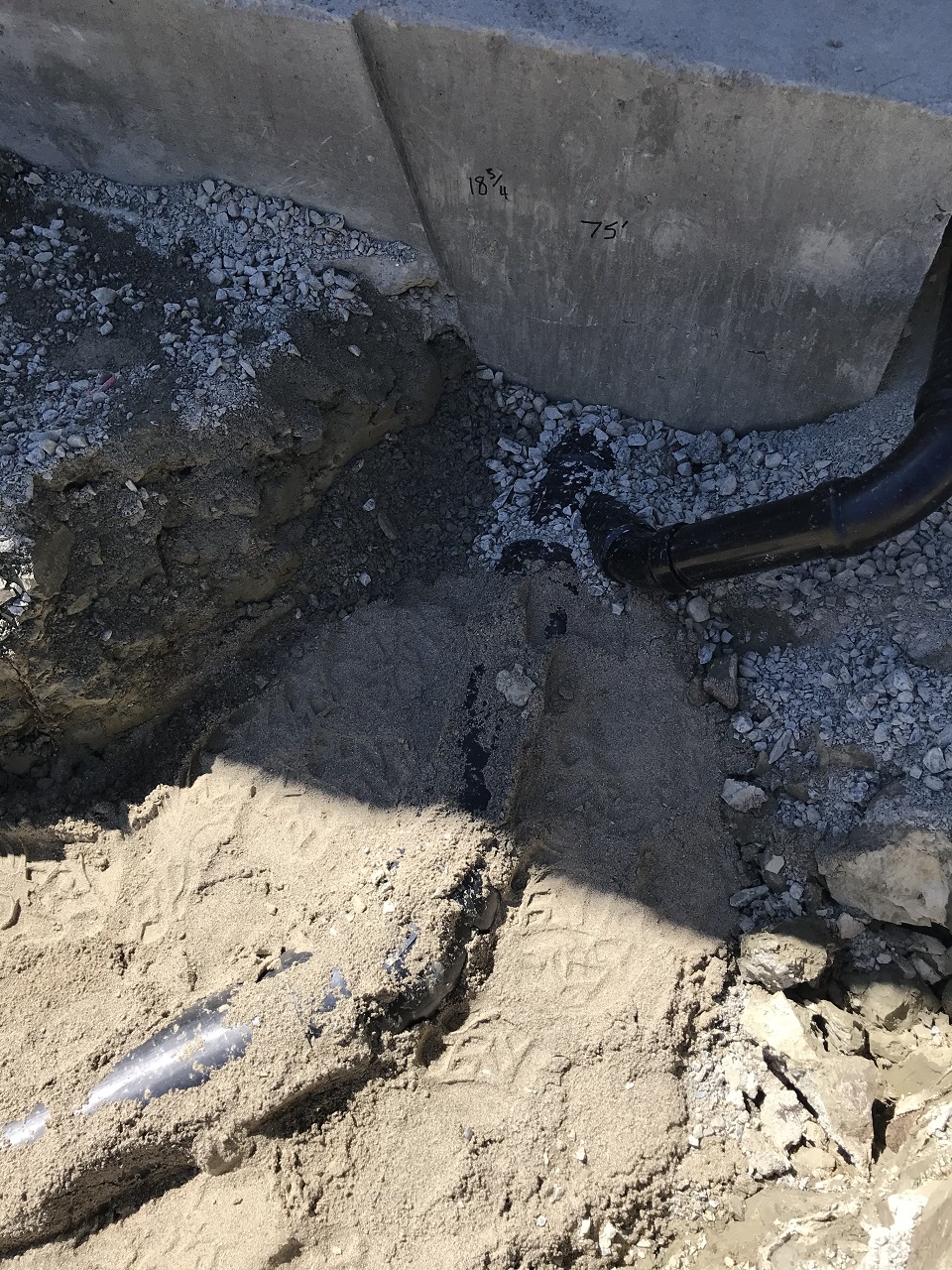
In the below photo, the 4" ABS building drain pipe exits the foundation footer through a sleeve that we placed during the original concrete footer pour (planning ahead for this day!):
The below photo shows a lot of preparation has been accomplished. We covered the ground and plumbing with a plastic vapor barrier, and then we placed crushed gravel on top of that, spraying it with water to better condense it as we placed it in 6" lifts, and we carefully ran our plate compactors over it. This is what is known as the sub-base. Careful placement and compacting will ensure that we pour the correct thickness of concrete (in this case 4") and that the concrete doesn't crack from being placed on a loose sub-base that settles under our slab. We have also tied up 1/2" rebar 24" on center in both directions to
create a grid. The rebar strengthens the concrete, and it also keeps it
strongly connected in a single plane in case there is any settling or
heaving (which we don't expect). That means even if it cracks somewhere, it
will not separate on the the vertical plane.
You may have noticed that we have some deeper sections where the concrete will be placed, and these have extra rebar. These are footers for load bearing walls or load bearing posts that will be placed on the finished slab during the framing phase. In the following photo is a footer pad with extra rebar that will support a load-bearing post above:
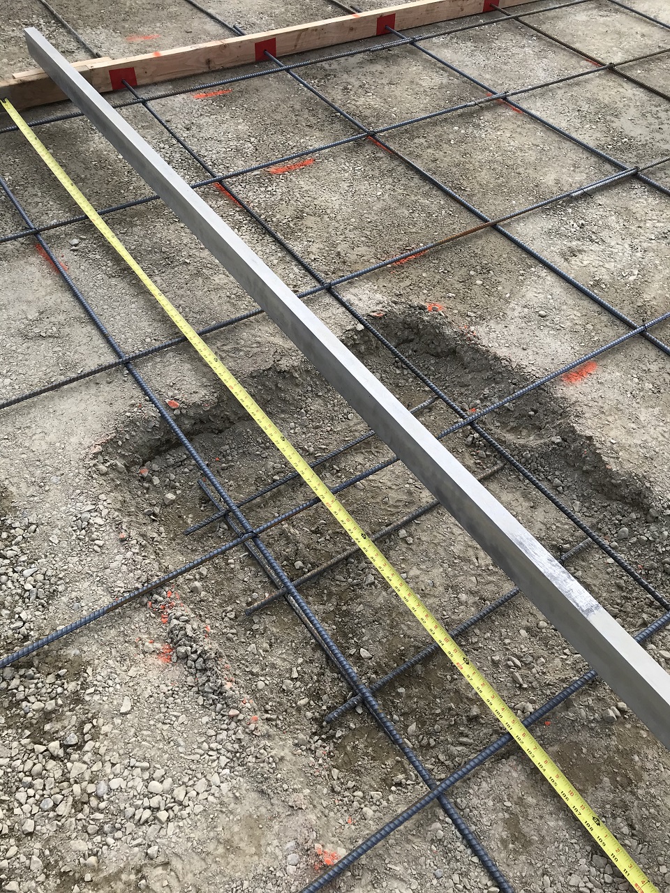
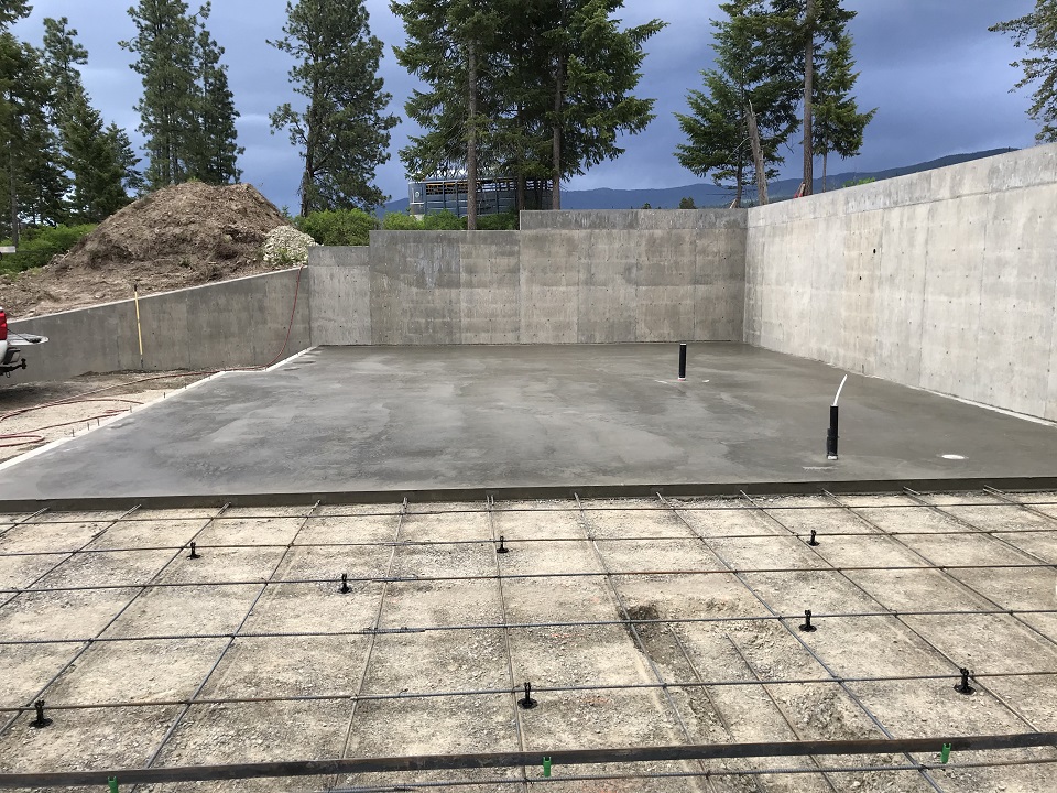
We have just poured and finished the 1st half of the slab below, we removed the 2x4 that separates it from the 2nd half, and we have wired up the rebar grid and set the steel screed rails for the second pour which will happen the next day:
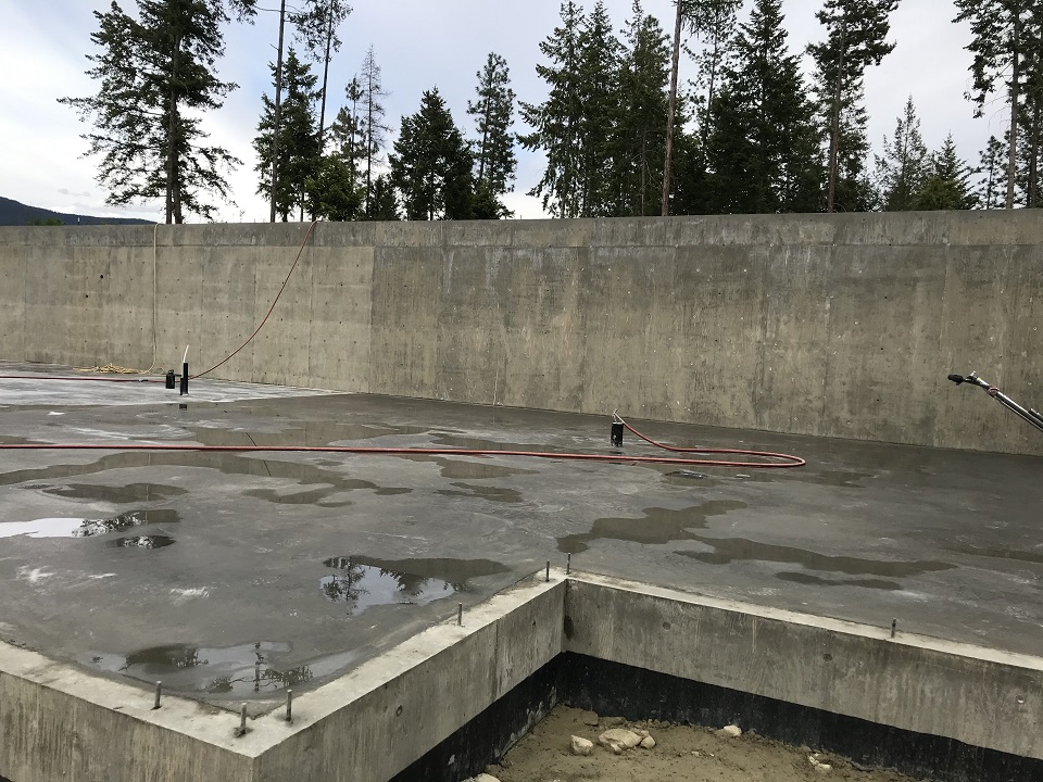
And below you can see the handle of our power trowel still on the 2nd half of the newly poured and finished slab. It had just rained late in finishing operations, but we were done at that point!
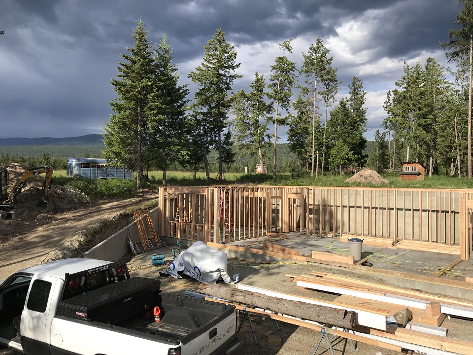
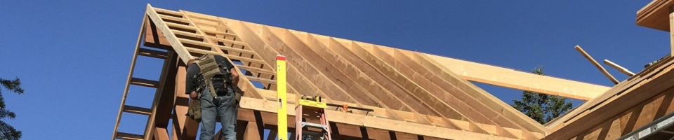
The basement wall framing has been delivered, and our first step is to lay out the walls using the plans, snap lines for the wall plates, and then plate and mark layout for all of the windows, doors and studs on both the bottom and top plates. Of course, all bottom plates that sit on the concrete are treated lumber, and the ones that sit on an outside stem walls get placed over a foam sill sealer to seal minor variations between the lumber and the concrete. When we poured the foundation we placed J bolts in all of the walls with which to bolt the plates, attaching the walls to the foundation. Out on the slab where walls get placed, we use a rotohammer to drill and place foundation bolts to attach the walls:
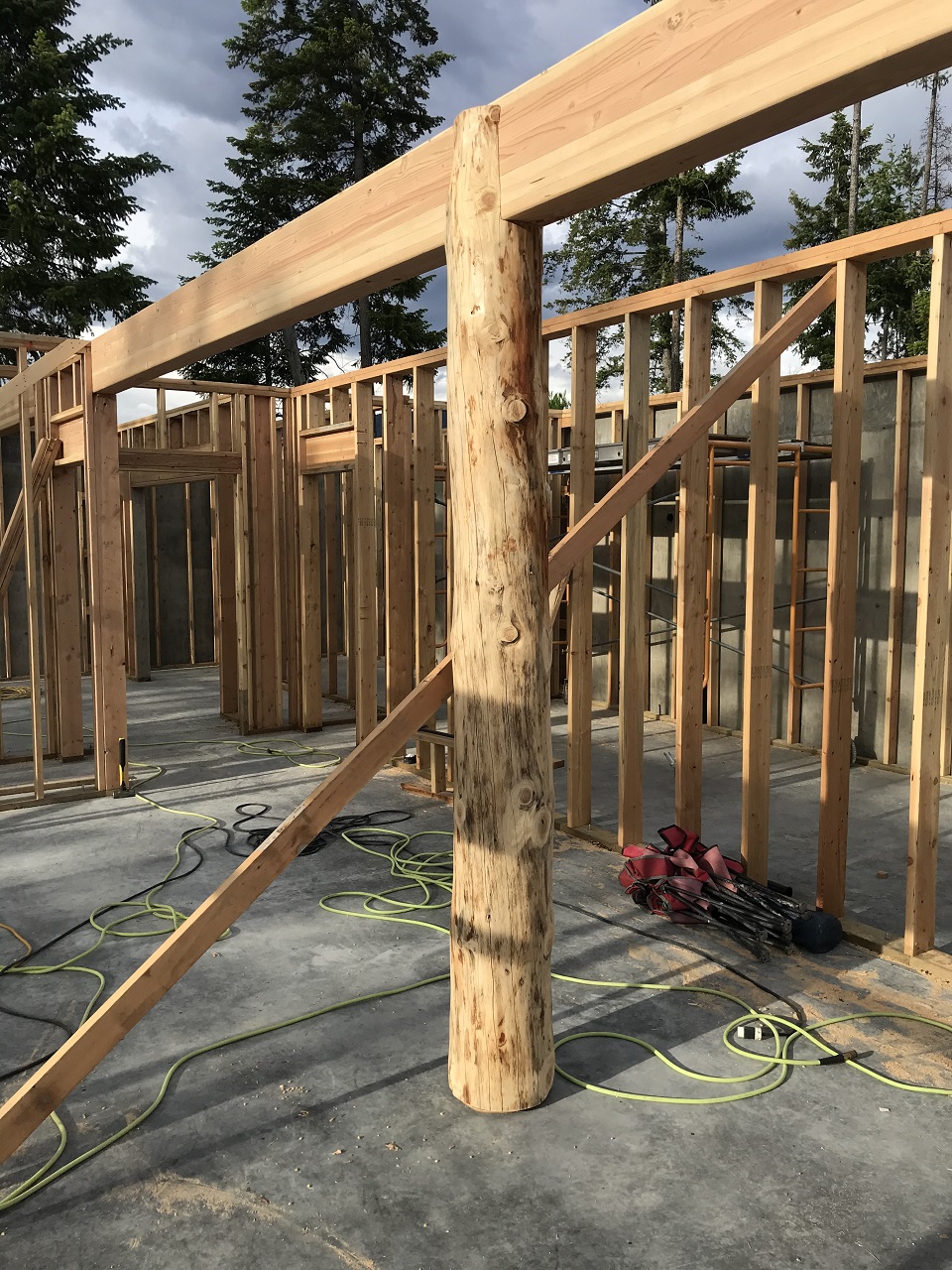
This is an interesting glu-lam beam to post connection. This will all be lacquered and be visible when the interior is finished. This post sits on one of those deep footer bases we accommodated when we poured the slab. It is actually sitting on a piece of treated plywood so that it, being untreated, is not in contact with concrete. There are also bolts sticking up into the bottom of the post to keep it in position on the floor even if it got a big push laterally:
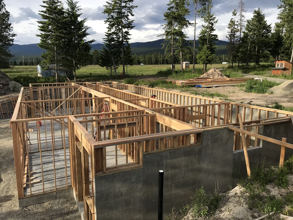
In the below photo, basement level walls have been framed and all double-top
plates have been installed. The walls have been braced plumb and square. The
next step will be to install the exterior plywood shear wall, some let-in
braces and some interior plywood shear wall. You'll notice we have not yet
waterproofed the exterior basement concrete walls and backfilled. We will do
that after we build the main floor deck is built. That way all of the concrete walls
will be braced for resistance to the backfill. The delay before backfill
caused by framing also
allows the concrete to begin curing and gain quite a bit of its designed
compressive strength before the backfill.
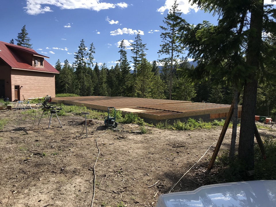
The i-joists are installed for the main floor deck, and we are ready to install the subfloor:
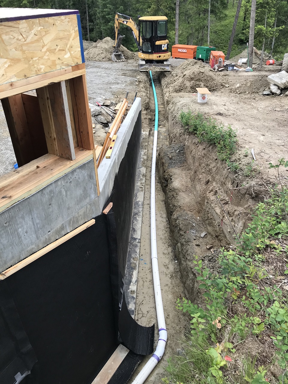
In the below two photos you can see two sides of the foundation with french drain pipes running out the hillside to daylight. A french drain is a perforated 4" PVC pipe placed at the level of the foundation footer and covered with drain rock and a filter fabris and fill. This drain allows water that gets to the foundation to escape to daylight rather than put hydrostatic pressure on the basement walls.
We have painted the retaining walls with asphalt emulsion and the basement
concrete walls have been treated with a primer, and then a roll, peel and
stick waterproofing membrane has been installed with lapped and sealed
joints, and a drain board with fabric has been placed over this
waterproofing. The drain board allows surface water to get to the french
drain efficiently.
We actually use 4" perforated PVC pipe at the footers to admit water into the pipe, but then we change to a solid walled pipe to run the distance that it takes to get to the hillside that we are exiting to daylight. In the below photo, that transition is where the white colored pipe changes to green:
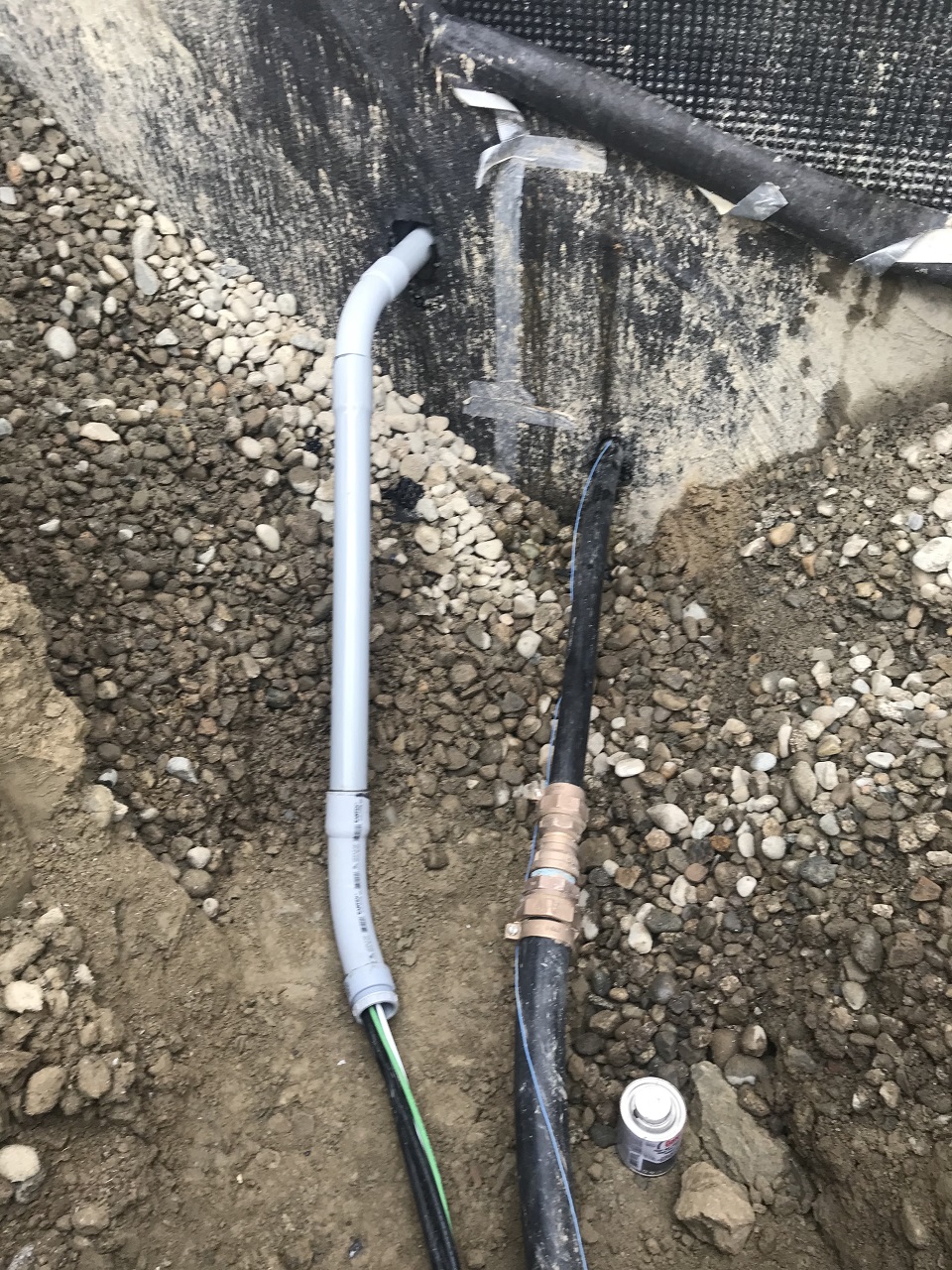
Now, we backfill, but also as part of that process we are going to place the water line and the electrical service through the sleeves we placed for them in the poured concrete basement walls (yes, your contractor should plan for all of these penetrations at the time he is forming the pour). We are in heavy clay soil here, and we learned years ago that in clay a direct bury electrical service entrance cable is better than placement entirely in conduit (our usual mthod). That is because the conduit will fill with water through even glued joints, and that water will run to the low spot, which in this case would be the panel in the basement! We do use a little conduit with a bushing to actually bring the cable through the wall. Note all that drain rock up against the basement wall to facilitate water passing through to the french drain. The rock also exerts far less pressure on the wall, especially hydrostatic pressure from saturated or frost heaved clay soils.
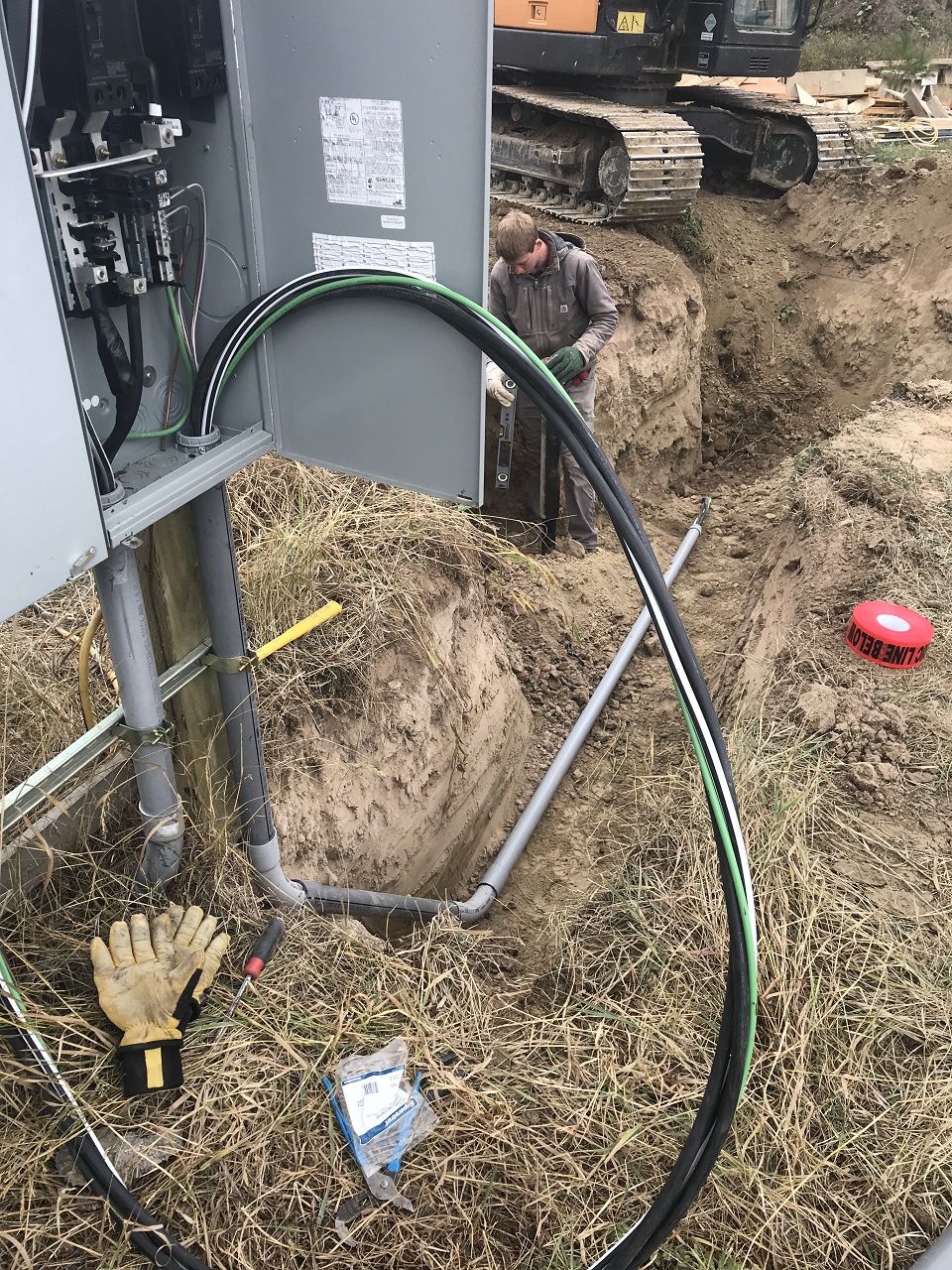
Making the electrical and water connections out at the water main line and the meter pedestal:
|